The PWM signal: A complete guide to pulse-width modulation – basics, math and applications
Digital logic dominates modern electronic systems, but many real-world devices – motors, lighting, sensors and audio systems – require analog control. Pulse-width modulation (PWM) is the technology that bridges this divide, using a digital waveform with a variable duty cycle to emulate analog levels.
This method rapidly switches the signal between a high and a low state and relies on the inertia of physical devices, or on a low-pass filter, to smooth the switching into an average voltage. PWM is fundamental to applications ranging from LED dimming to efficient DC-DC converters and class D amplifiers.
Understanding the basics of PWM
Definition and duty cycle
A PWM signal is a digital waveform that switches between a high voltage (VH) and a low voltage (VL). The period (T) is the reciprocal of the frequency (f): T = 1 / f.
Within each period, the signal stays high for a time ton and low for toff = T − ton.
The duty cycle (D) is the fraction of the period during which the signal is “ON” (high):
D = ton / T × 100%
Adjusting D directly changes the average output voltage seen by the load. If the low level is ground, the average value is:
Vavg = D · VH
Because the switching is fast, inertial loads (such as motors or the human eye) integrate the waveform, perceiving a continuous level proportional to the duty cycle. This linear relationship makes PWM extremely attractive for digitally approximating analog levels.
Frequency considerations
The switching frequency is critical. It must be high enough that the load can't follow the individual pulses.
- LED lighting: Frequencies above 50–90 Hz are needed to avoid visible flicker, and hundreds of hertz are typically used.
- DC motors: Frequencies from a few kilohertz to tens of kilohertz are used to avoid audible “whining” and reduce torque ripple.
High frequencies reduce output ripple and allow smaller filter components, but they increase switching losses and electromagnetic interference (EMI).
Generating PWM and types of PWM
Generation methods
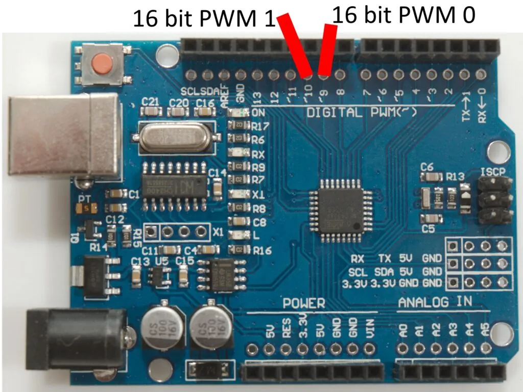
- Microcontroller modules: Modern microcontrollers have dedicated PWM peripherals that generate signals autonomously. Setting the top value controls the period/frequency, and the comparator value sets the duty cycle.
- 555 timer: Before microcontrollers became ubiquitous, engineers often used the NE555 timer in astable mode to generate PWM.
- Software PWM: Without hardware modules, PWM can be implemented by toggling an I/O pin using timer interrupts, which is suitable for low-frequency applications.
Different PWM techniques
PWM type | Description | Applications |
Single-edge | The pulse starts or ends at a fixed point. Easy to implement, but can cause EMI. | Simple LED dimming, basic motor control. |
Center-aligned | The pulses are centered in the period, with both edges moving symmetrically. Reduces harmonic content and spreads out the switching transitions. | Motor control, half- and full-bridge converters. |
Sinusoidal (SPWM) | The duty cycle is modulated by a sinusoidal reference to approximate a sine wave. | AC motor drives, inverters. |
Mathematical foundations and resolution
Ripple and filtering
In practice, the load doesn't see a perfect DC level but a waveform with ripple. With inertial loads (a motor), the mechanical time constant acts as a low-pass filter. For purely electrical loads, RC or LC filters are used to suppress the switching frequency.
From the point of view of Fourier series, the PWM waveform contains a DC component plus harmonics at multiples of the fundamental frequency. Increasing the frequency (f) pushes these harmonics further away from DC, which makes filtering easier (a smaller filter can be used) but, as mentioned, increases switching losses.
Duty cycle resolution
Digital PWM generation has a finite resolution, which depends on the bit width of the timer counter (N): the step is 1 / (N + 1).
- 8-bit PWM (N=255) provides a step of ~0.39%.
- 16-bit PWM provides much finer control but requires a higher clock frequency and increases hardware complexity.
Engineers need to choose a resolution that suits the application – 8 bits for LED dimming, but 16 bits for precise motor control or audio synthesis.
Practical applications in engineering
Controlling DC motors and servo motors
The speed of a DC motor is proportional to the average voltage. PWM provides this control with minimal power loss, because the power transistor operates in switching mode.
Servo motors use PWM a little differently: the pulse width, not the average voltage, encodes the position. With a typical servo, a 1 ms pulse is 0°, 1.5 ms is 90° and 2 ms is 180°, with a period of about 20 ms (50 Hz).
DC-DC conversion and power management
Switch-mode power supplies (SMPS) such as Buck, Boost and Buck-Boost converters use PWM to regulate the output voltage. Through feedback, the duty cycle of the switching transistor is adjusted to keep the voltage stable as the load changes. PWM is also key to class D amplifiers and battery management systems (BMS).
Conclusion
PWM is a cornerstone of modern electronics, allowing digital systems to control analog quantities with high efficiency and precision. Given the rapid growth of the microcontroller, electric vehicle and IoT markets, pulse-width modulation will remain a vital tool for engineers.
On the Artec Robotics “News” page you will find a variety of articles and guides on robotics and automation. Here you'll find useful information about the latest technologies, software solutions and programs. They will help you dive deeper into the world of industrial robots and automated systems.
Follow the news from Artec Robotics!
MAKE AN INQUIRY